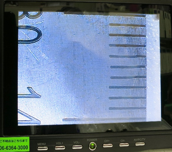
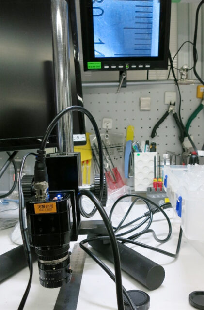
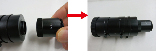
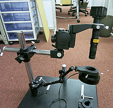
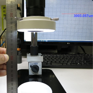
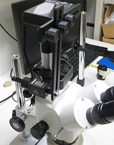
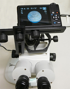
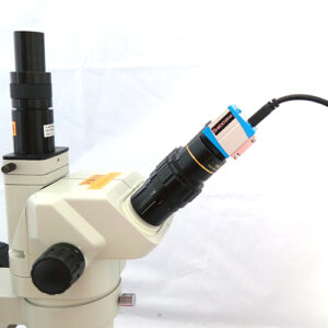
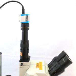
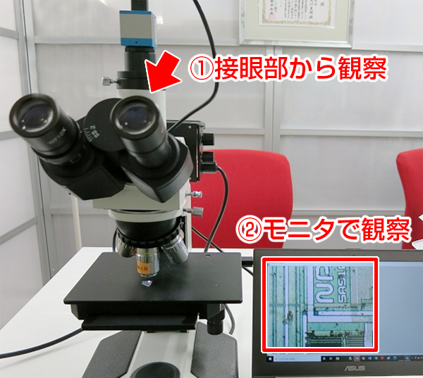
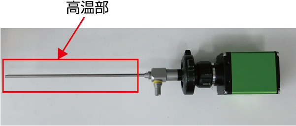
In the observation section (high-temperature area), a bore is installed, and a camera is connected to the end of the bore for observation.
The following two methods are the main methods.
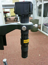
Without cooling device
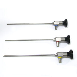 |
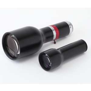
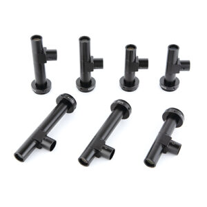
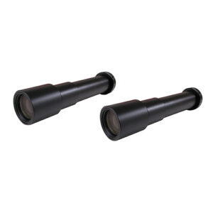
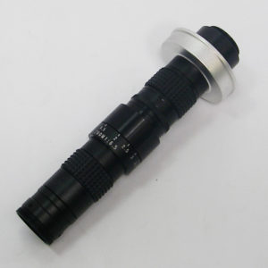
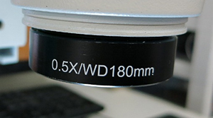
120℃ compatible borescope (φ4.0mm) Click here for product details
●Heat-resistant borescope that can handle up to 120℃ |
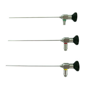 |
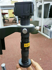
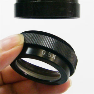
120℃ compatible borescope (φ2.7mm) Click here for product details |
The compatible temperature is 120℃, but it is usually in stock and low price.
If it is a made-to-order product, we have borescopes that can handle up to 150℃.
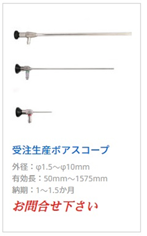
Please refer to the website for details.
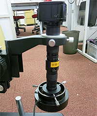
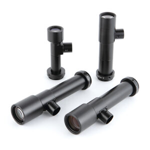
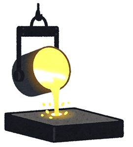
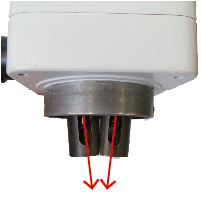
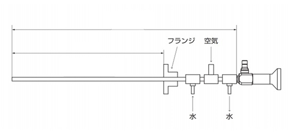
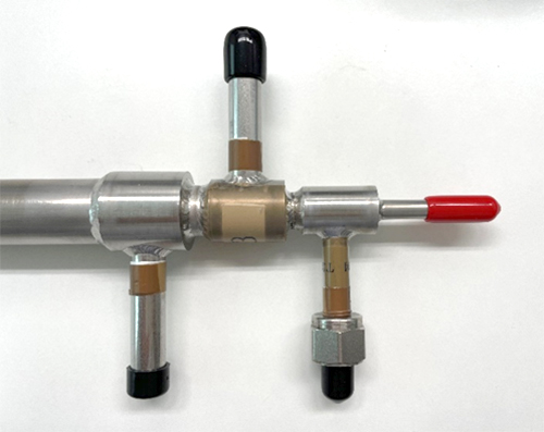
With cooling device
By attaching a cooling device to the borescope, it can withstand significantly high temperatures. It can even handle ultra-high temperatures exceeding 2000°C. This can be achieved by covering our borescopes with a heat-resistant jacket (custom-made) for borescopes with a diameter of φ4mm or larger (please refer to our website for details).
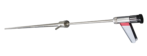
The ultra-heat-resistant borescopes are mostly made to order. After detailed discussions with the customer, production will commence. However, please note that the price for these custom-made products can reach several million yen.
For further details regarding the borescopes, please feel free to contact our technical staff at shodensha. We are more than happy to discuss your requirements and provide individual proposals tailored to your company’s needs.