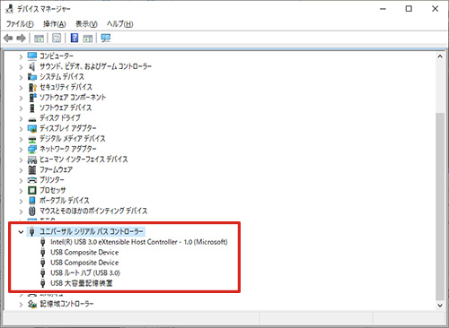
It is possible to connect four USB 2.0 5-megapixel cameras simultaneously, such as the DN2R-500. However, there may be limitations on frame rates and other factors depending on the application.
Primarily, bandwidth considerations should be taken into account, followed by an evaluation of the power and compatibility between the PC’s CPU, memory, USB host controller performance, and the load of all four cameras.
For instance, if one 5-megapixel camera operates at 5fps, the bandwidth required is approximately half of the USB 2.0 host controller’s capacity, assuming a theoretical maximum of 500Mbps. In practice, the effective bandwidth is around 360Mbps, so the usage is already over half of the available bandwidth.
Operating at 1fps or having four USB host controllers might make it feasible, but the actual performance depends on the PC. Therefore, it’s essential to evaluate the setup practically.
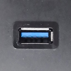
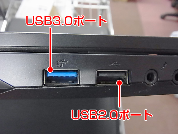
For simultaneous operation of four cameras, using USB 3.0 would be preferable. With USB 3.0, a single host controller can provide 5Gbps (5000M), allowing sufficient bandwidth for simultaneous connections, even with a hub.
Though consumer-grade hubs are prevalent, they may introduce uncertainties. For industrial applications, PCIe boards with multiple USB 3.0 ports are commonly used. These boards provide a stable and reliable solution, albeit at a higher cost than consumer-grade alternatives.
For instance, using a PCIe board with four USB 3.0 ports is a common approach. While consumer-grade options are available, industrial-grade boards from companies like AVAL DATA offer long-term supply and stability but come at a higher price.
Utilizing motherboards with built-in USB 3.0 ports is another option. However, performance-wise, a four-channel PCIe board is the most stable solution.
Connecting and processing images from four cameras can significantly strain the PC’s resources, so the intended usage scenario should also be considered. For instance, USB 3 Vision models impose the lowest CPU load, followed by USB 3.0 and then USB 2.0 models, respectively.