・what is welding?
Welding is defined as the process of joining two metal substrates at their junction using heat, pressure, or other methods, or alternatively, joining them by incorporating filler material under heat or pressure.

The primary methods commonly used for heating in welding include electricity, arc discharge, gas, plasma, and laser techniques.
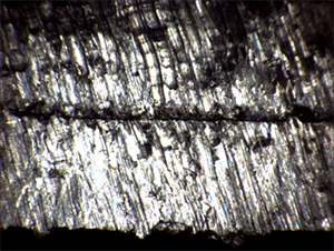
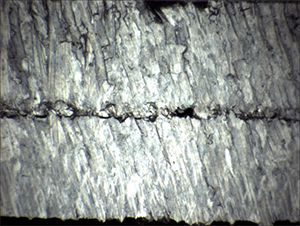
In this process, the weld bead length formed in the weld (weld deposit) significantly affects the strength of the weld joint.
・Evaluation of welding
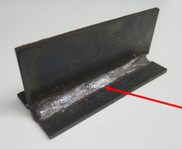
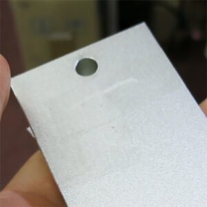
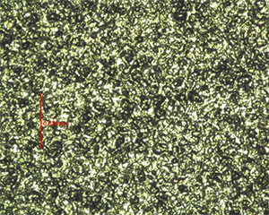
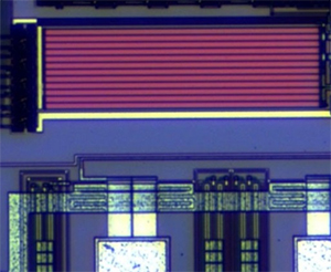
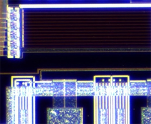
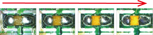
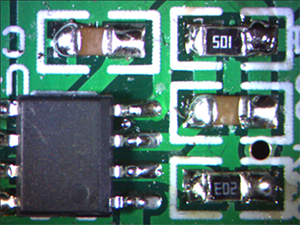
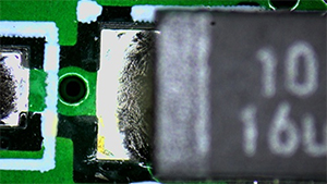
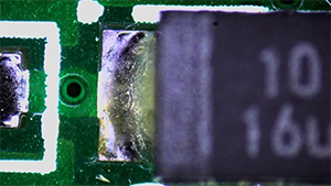
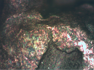
The portion of the weld where material has been deposited, indicated by the red arrow in the image, is known as the weld bead.
Depending on the welding conditions, the appearance and dimensions (width, length, height) of this weld bead can vary.
The shape of the weld bead allows for the evaluation of whether the welding was performed correctly and if there are any welding defects.
Common welding defects include:
– Insufficient reinforcement
– Overlap
– Undercut
– Porosity
– Cracks
To evaluate this weld bead, it is necessary to measure its three-dimensional shape.
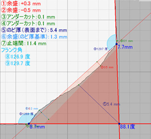
– Inspection in welding involves specifying dimensions in the weld section. This includes the minimum thickness of the weld bead, known as the “throat thickness,” and dimensions such as the “penetration” and “fusion depth,” which measure from the melted metal peak to the surface of the parent metal.
– For more information on measuring weld penetration, click here.
Among the specified dimensions is the “leg length (kyakuchou),” which extends from the weld root section to the end of the weld bead. This leg length serves as one of the criteria for determining the optimal bead width.
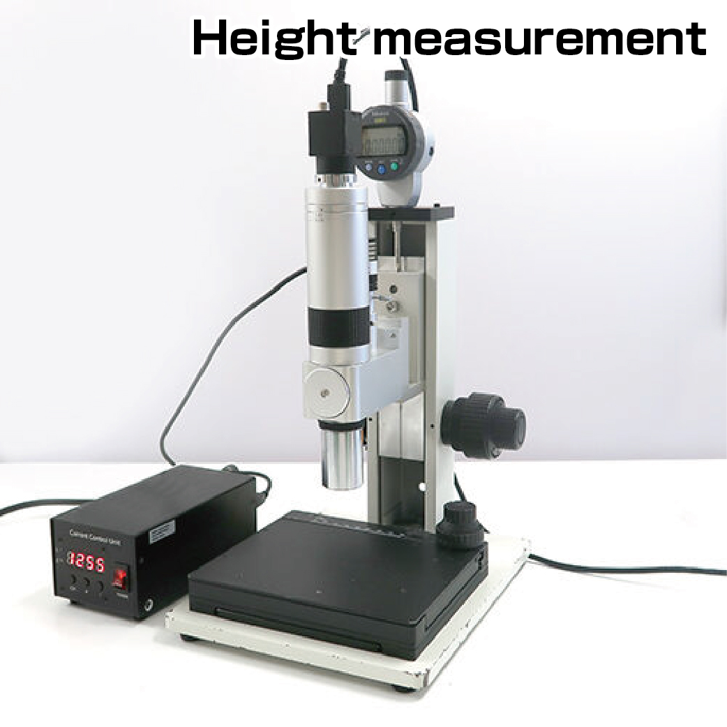
Efficiency in measuring the shape and length of weld bead legs.
To ensure welding quality, it is necessary to inspect the weld bead.
Common inspection methods include:
– Visual comparison with a reference sample
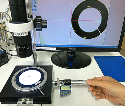
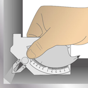
– Comparison using a welding gauge and visual inspection
These methods often require high skill from inspectors and can be time-consuming. Moreover, judgments may vary depending on the individual.
Additionally, using welding-specific gauges for measurements requires multiple measurements at various points, which is inefficient.
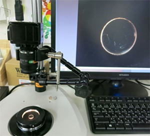
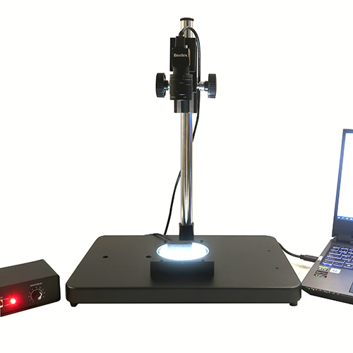
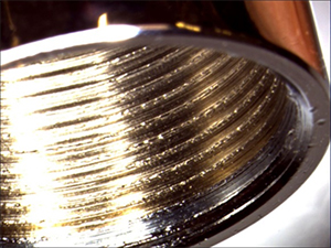
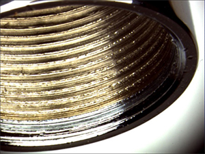
<Image of welding gauge measurement>
Utilizing the following product can resolve issues related to measuring weld bead lengths:
Recommended product for weld bead length (bead) measurement:
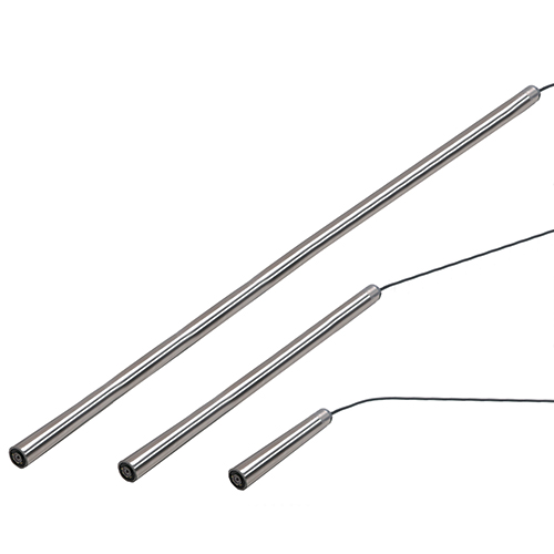
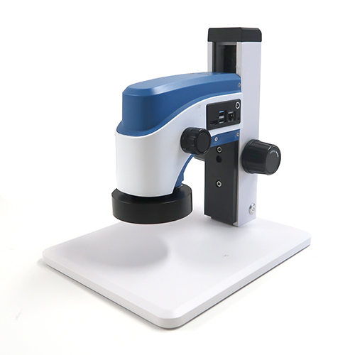
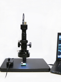
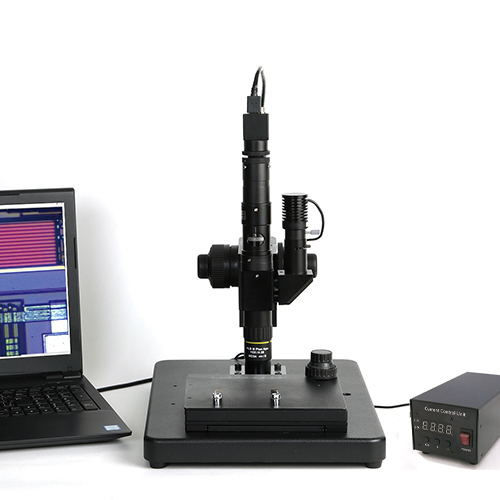
【Weld Bead Length Handy 3D Scanner CSM-HS10WL】
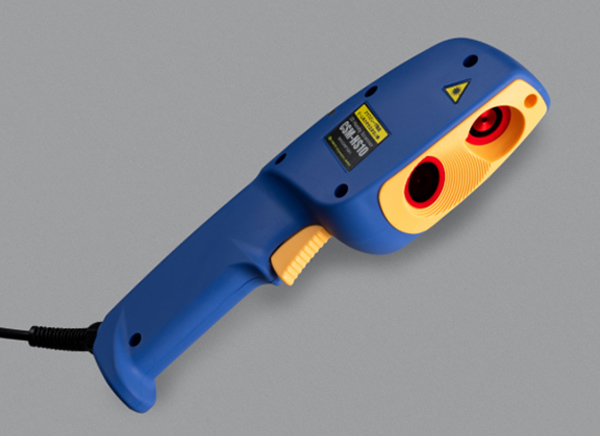
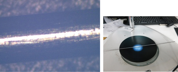
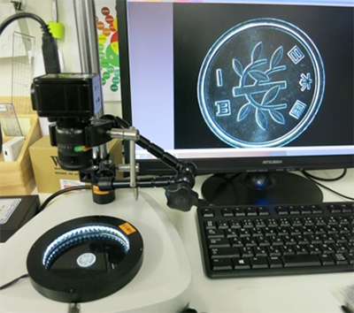
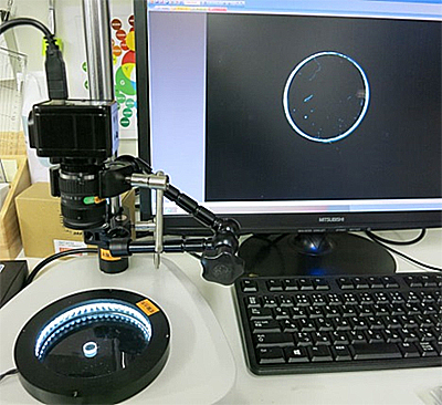
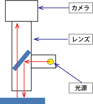
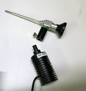
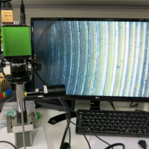
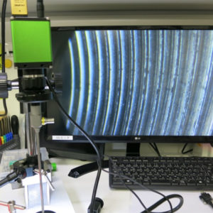
This product is a 3D handheld scanner that allows instant, non-contact and non-destructive measurement of weld bead cross-sections simply by aiming a laser at the weld area to be measured.
*Note: It cannot measure penetration depth inside the weld or internal blowholes.
No need for rulers or welding gauges; it operates using a non-contact optical cutting method triggered by a switch.
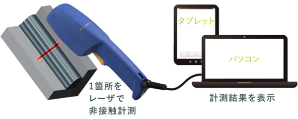
You can scan the 3D shape of the laser irradiation line applied to the weld area and measure the cross-sectional view with high accuracy. This allows for instant, non-destructive measurement of weld bead (leg length) without human error or variability.
~ Features of this device include:
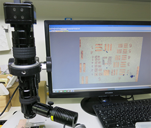
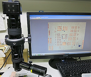
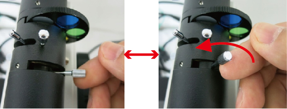
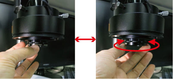
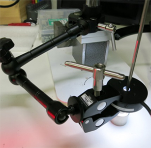
Feature 1: Easy-to-use handheld 3D scanner
– Simply connect to a PC or tablet via USB. Once the welding measurement software built into the device is installed on the PC, it can be operated immediately.
– Being handheld makes it easy to handle, allowing measurement of targets that were previously difficult to measure, including large or heavy objects and narrow spaces.
Feature 2: Measurement by simply aiming and triggering
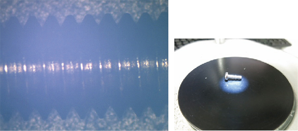
– When measuring weld beads, conventional methods require the use of a square or welding-specific gauge. With this device, precise measurement with pinpoint accuracy is possible with a single laser shot.
– Simply aim at the weld bead (weld protrusion), pull the trigger switch, and the measurement is done.
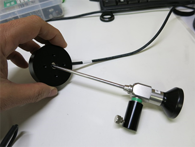
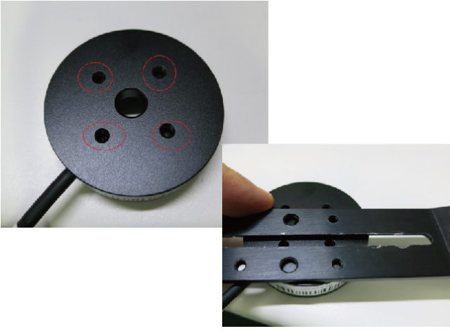
– Comes with a detachable guide rod for convenient adjustment of distance and angle during measurements.
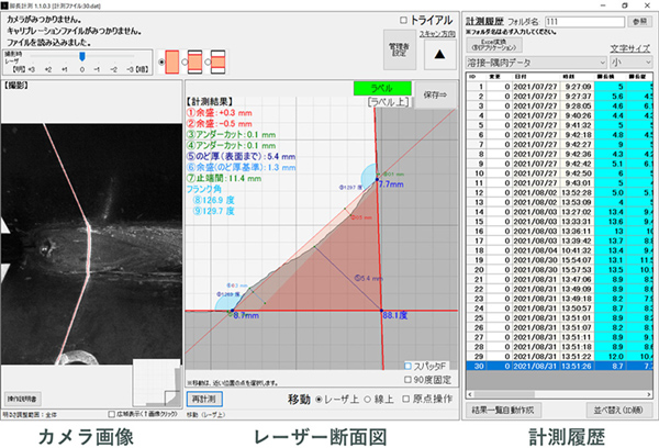
– Easily perform 3D measurements of 12 points including “leg length,” “undercut,” “joint angle,” and “excess buildup” using the optical cutting method.
Feature 3: Instant display and saving of leg length measurement results on PC screen
– Measurement results can be saved as files and the data can be utilized in Excel®.
– Numerical results are displayed simultaneously during measurement, ensuring accurate and error-free records.
– Eliminates the need for handwritten records that can be prone to errors and enhances security against tampering.
– Allows for traceability assurance.
~ Additional Convenient Features ~
Feature 1: Equipped with a standard measurement mode convenient for inspecting weld bead (leg length)

・角R(アール)の計測
・Measurement of butt welding
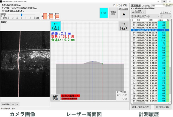
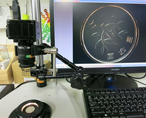
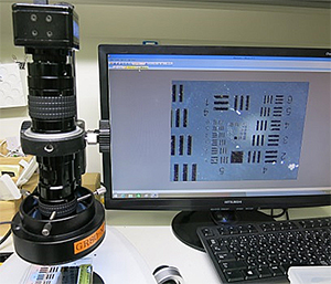
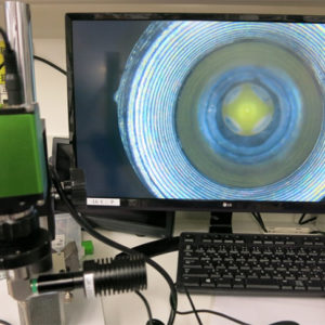
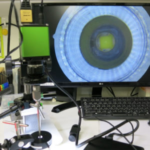
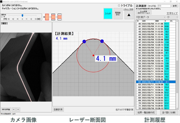
Feature 2: Displaying camera images, laser cross-sectional views, and measurement results on a single screen
-
・Camera Image:
Displays the captured video of the section through the camera.
・Laser Cross-sectional View:
Clearly displays measurement results with numerical data and cross-sectional diagrams.
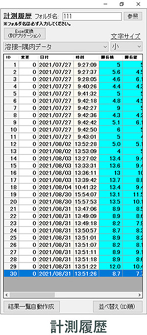
・Measurement History:
Displays numerical results of measurements.
Feature 3: Measurement history can be exported to Excel®.
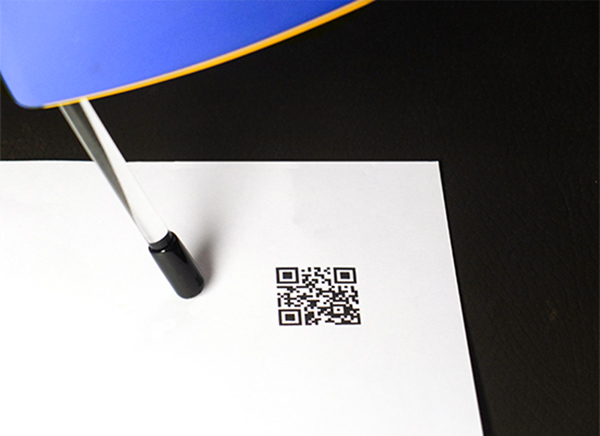
Feature 4: QR Code Reading
Allows easy linkage of measurement results with target items by scanning QR codes or barcodes. This enables the management of measurement results via QR codes.
Additionally, combining QR codes with cloud services enables visualization and digital transformation (DX) of welding operations.
・Summary
If you want to significantly improve and streamline the challenging task of measuring weld bead shapes accurately,
The 【Weld Bead Length Handy 3D Scanner CSM-HS10WL】is incredibly convenient.
・Eliminates variability in measurements by individuals, ensuring quantitative measurement.
・Capable of reading QR codes and linking with product data.
・Enables instant and accurate 3D shape measurement of objects without contact.
・Visualizes anomalies in weld bead areas using color maps.