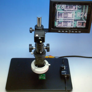
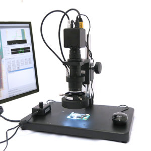
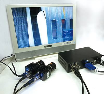
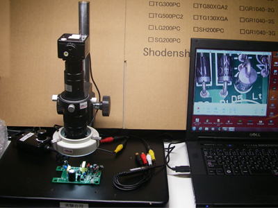
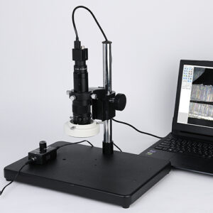
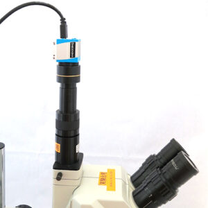
I want to display crosslines with a high-definition microscope!
When it comes to creating lines within images for alignment or using them as reference lines, many of you may be aware that it can be done with a line generator. However, in the end, preparing a separate line generator in addition to the camera and lens can unexpectedly increase the cost.
The camera we use in our high-definition microscope already has this line generation feature as a standard. Therefore, you can easily and affordably generate lines without any additional expenses.
What is a High-Definition Camera Capable of Cross Display?
Each camera in the High-Definition Microscope comes standard with a crossline display function. In this case, a separate line generator is not needed, and crosslines or crosslines at any desired position can be generated using only the functions of each camera.
We will introduce each camera individually.
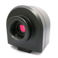
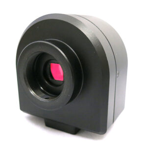
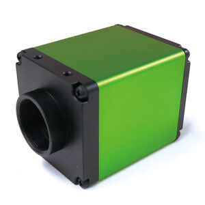
① HIGH-PERFORMANCE FULL HD (HIGH-DEFINITION) CAMERA XM200HD
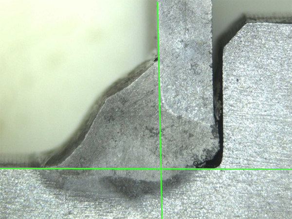
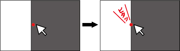
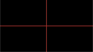
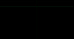
For the XM200HD, it generates a center crossline in the middle of the screen. The line color is red, and you can’t change the color of it. You can toggle the line display on and off.
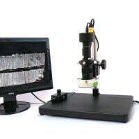
Microscopes using the XM200HD include:
・High-Function High-Definition Microscope TG200XM
・High-Function High-Magnification High-Definition Microscope FZ200XM
・High-Function Low-Magnification High-Definition Microscope LRS200XM-MC1
・High-Function Long-Distance High-Definition Microscope (Stand Type) LRA200XM-S
・High-Function Long-Distance High-Definition Microscope (Edge-Fixed Type) LRA200XM-E
・High-Function Coaxial Illumination High-Definition Microscope Z200XM
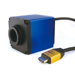
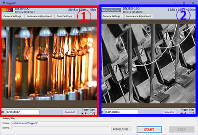
② Hybrid High-Definition Camera (with measurement and drawing functions) GR200HD2-MePRO
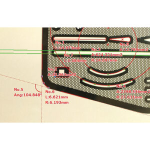
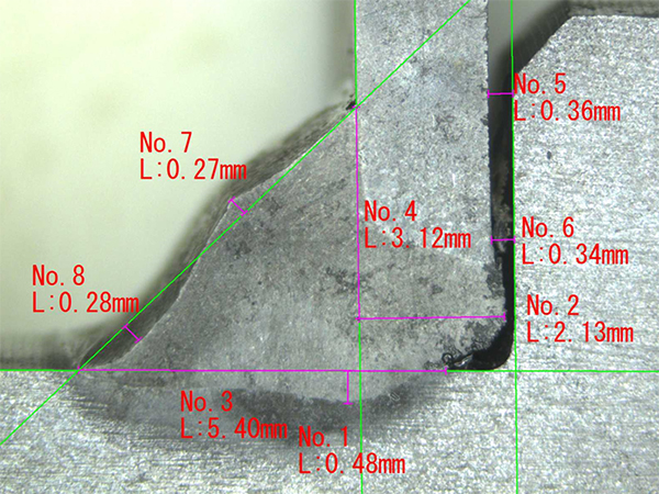
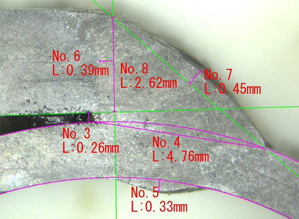
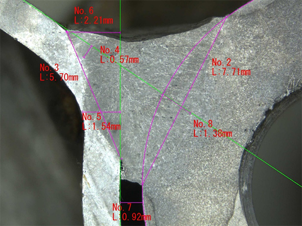
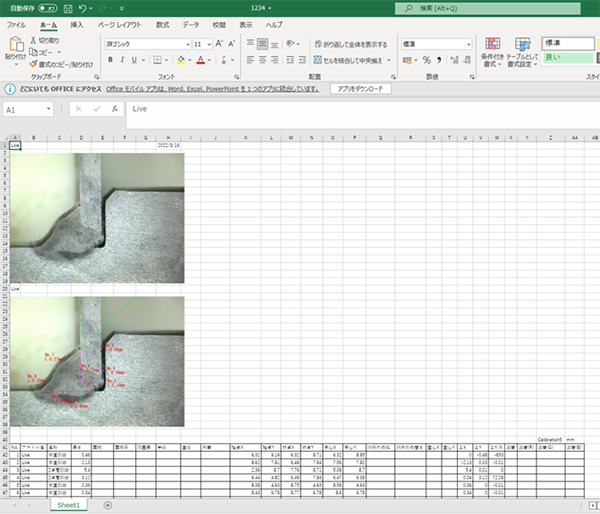
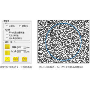
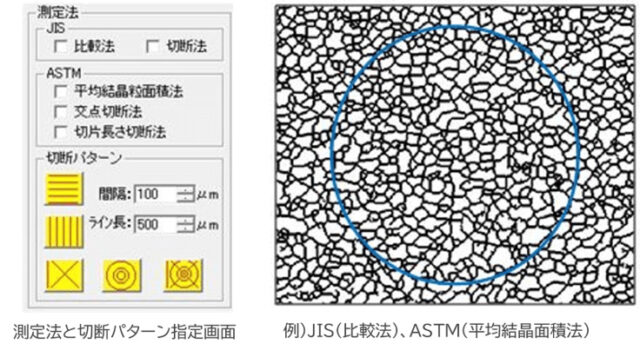
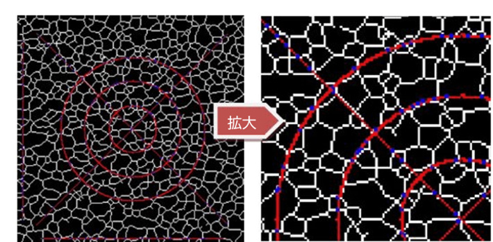
For the GR200HD2-MePRO, it’s a high-definition camera with line generation capabilities (custom crosslines, concentric circles, angle lines) and measurement functions. Line generation is possible at any position, including concentric circles and angle lines. You can choose from 5 different line colors. This model also comes with measurement capabilities.
Microscopes using the GR200HD2-MePRO include:
・Multi-Function Hybrid Microscope TG200HD2-MePRO
・High-Magnification Multi-Function Hybrid Microscope FZ200HD3-MePRO
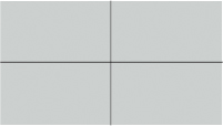
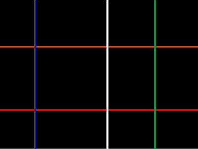
For the BA200HD, it’s a high-definition camera with both custom line generation and crossline generation capabilities. Line generation is possible at any position, and you can also generate a center crossline in the middle of the screen. You have the option to choose from 5 different line colors. It can generate up to 4 vertical and 4 horizontal lines.
Microscopes using the BA200HD include:
・Low-Cost High-Definition Microscope TG200BA
・High-Magnification Low-Cost High-Definition Microscope FZ200BA
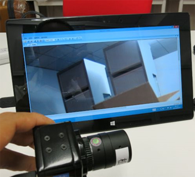
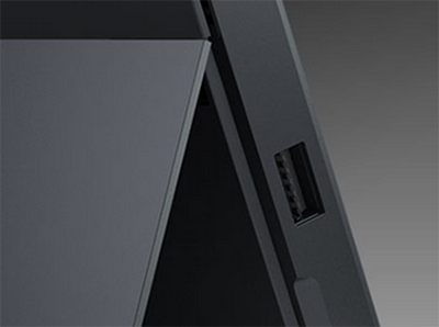
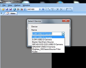
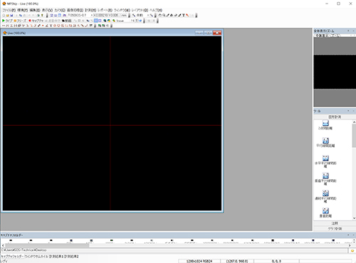
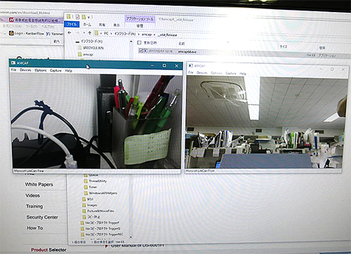
In the case of a USB microscope camera
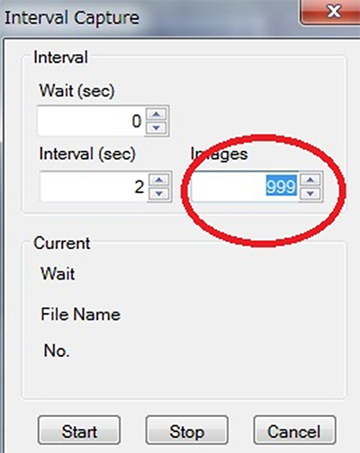
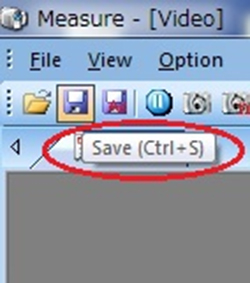
In the case of a USB microscope camera, you can use the optional viewer software (MF Ship) to display multiple crosslines.
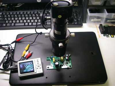
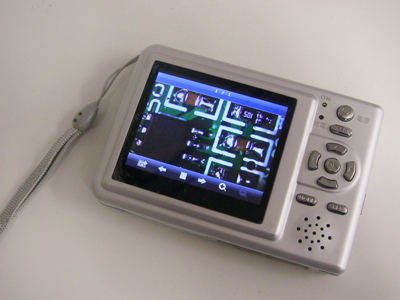
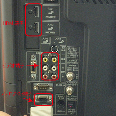
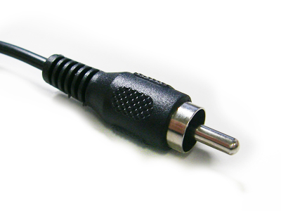
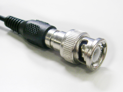
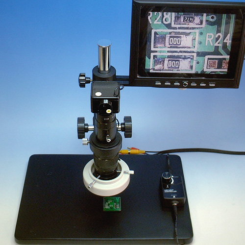
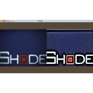
In the case of a video microscopes
As for video microscopes, a line generator is required.
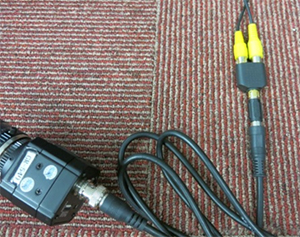
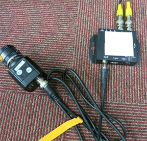
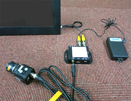
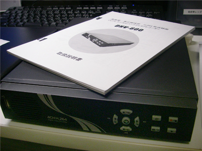
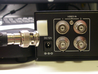
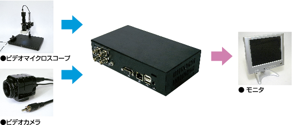
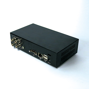
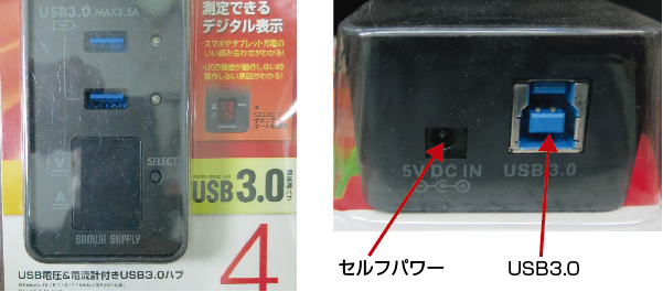
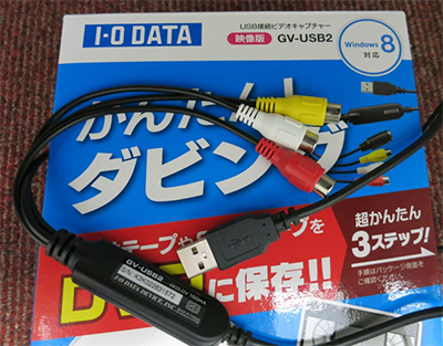
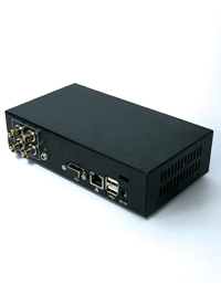
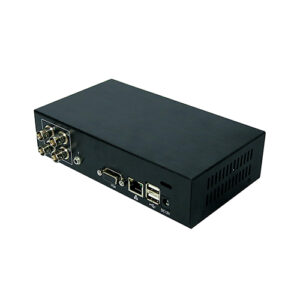
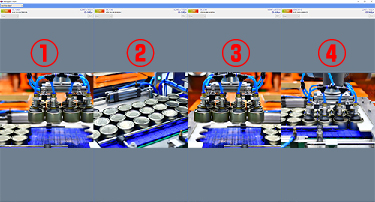
In our company, we also sell a line generator (USB memory-compatible video recorder with split function) GRAV-1.
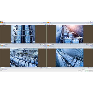
Optional line generation capabilities, dual-screen display (left/right or top/bottom), still image and video capture, and external trigger-compatible line generators are also available.
With this setup, positioning and alignment with two cameras becomes effortless.
Summary
In summary, there are numerous high-definition cameras (microscopes) available that integrate a camera with a line generator for tasks like alignment. You can choose the one that best suits your needs.
As an extra, there are methods involving USB cameras and software, as well as methods using video cameras and line generators.