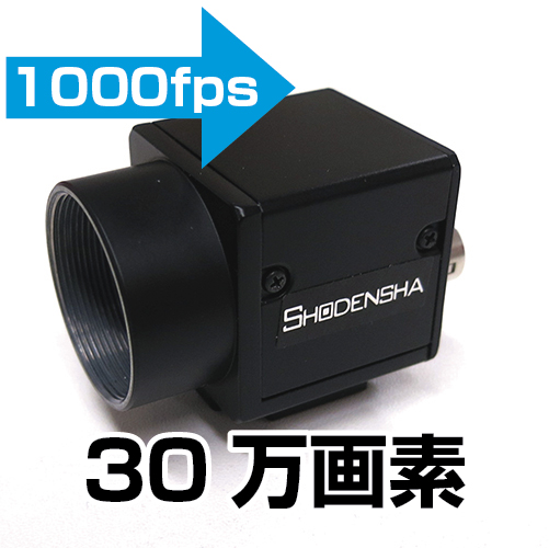
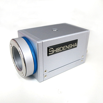
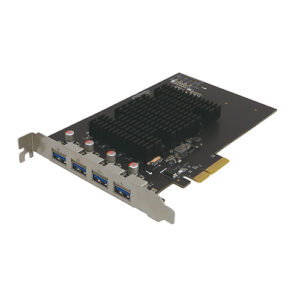
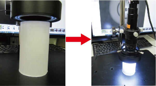
■ What are the external trigger terminals for industrial cameras?
Many industrial cameras have external trigger terminals.
 |
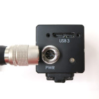 |
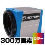
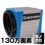
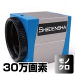
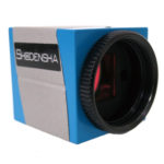
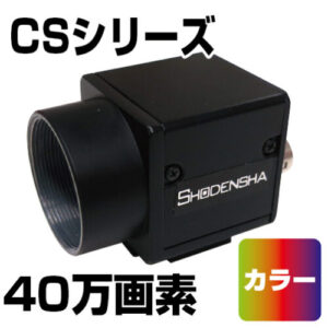
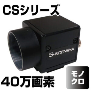
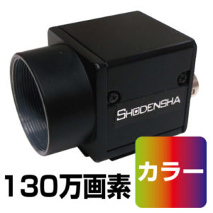
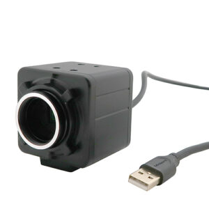
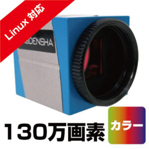
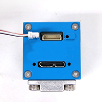
| USB Camera DN Series | USB Camera CS Series |
This trigger pin is used to control the timing of still image shooting and video recording with a sensor or PLC (programmable logic controller).
Watch the video brief image below.
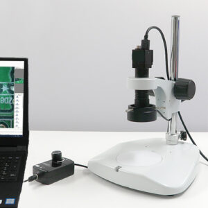
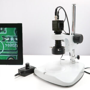
System Example Video
Of course, even if you don’t use an external trigger, you can use the included application software to save still images and record videos.
However, in actual production lines, it is common to shoot and record at the timing of the object to be photographed, and there are many situations where an external trigger terminal of an industrial camera is required.
Watch the video brief image below.
■ How to use the external trigger terminal?
When using external trigger terminals, there are various ways to use them depending on the customer’s production line.
In addition to simply saving still images and recording videos, it can be used for a variety of purposes, such as recording videos before and after a problem occurs, or shooting and recording with multiple cameras.
Therefore, when using an external trigger pin, it is basically assumed that the customer will program it himself.
Industrial cameras usually come with an SDK (Software Development Kit) for development, which is used to create programs.
■ Still image storage with external trigger
I mentioned that “basically create a program”, but if it is a simple function, application software can be used.
By using it, you can build a system without any knowledge of programming.
Among them, we will explain the most basic “saving still images with an external trigger”.
Even with the simple function of “saving one still image when an external trigger signal is input”, there are two main methods.
And the time display between the trigger and the next trigger is different.
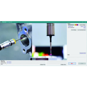
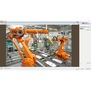
(1) A still image taken with the latest trigger is displayed between the trigger and the next trigger.
・Saved images can be reliably checked in real time.
Even lines with movement can be visually checked using still images.
・When shooting with multiple cameras at the same time, it is possible to shoot perfectly in sync.
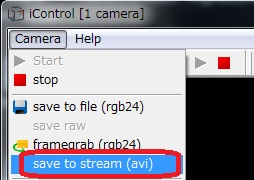
We offer the following software:
 |
 |
|
Trigger Shooting Software Hi TriggerF Light |
High-performance trigger shooting software Hi TriggerF Pro |
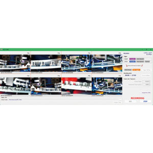
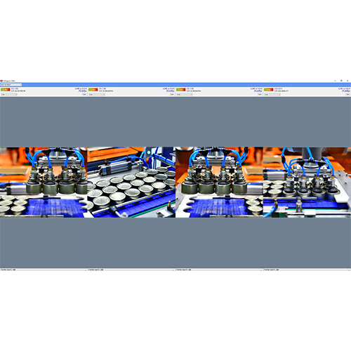
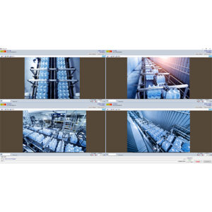
(2) A method is adopted in which live video is displayed between the trigger and the next trigger.
・Since the live image is always displayed, it is possible to monitor the status of lines other than the object.
・When shooting with multiple cameras at the same time, multiple frames may be out of alignment.
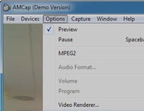
We offer the following software:
 |
|
Four-screen display shooting software Hi TriggerQ |
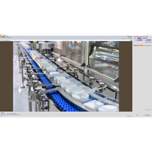
■ Video recording with external triggers
In the case of video recording, there are the following two types.
(1) Use the start trigger and stop trigger as triggers
(2) Use only the start trigger as a trigger
In the case of (1), only a simple recording function is provided.
In the case of (2), various functions are available.
In addition to simply recording the specified time by timer control from the trigger, you can also record before and after the trigger (operation like a drive recorder). It is useful for event analysis when a problem occurs.
We offer video recording software that allows you to use both Start/Stop triggers, timers, etc.
 |
|
Long-Duration Recording Software Hi TriggerRec |
Software to record video before and after the trigger
 |
|
Facility monitoring drive recorder Hi TriggerWatcher |