When performing dimension measurement using transmitted light, the appearance can vary depending on the “type of transmitted light” and the “brightness” used.
This article introduces the “recommended light” and “brightness” for dimension measurement using transmitted light, so please be sure to read it through to the end.
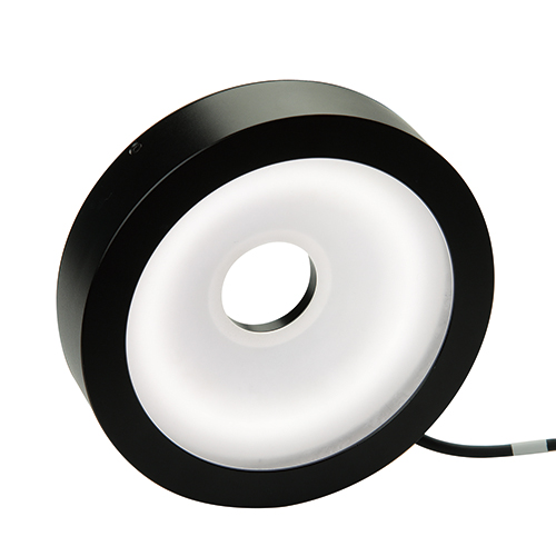
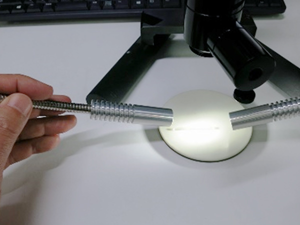
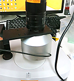
・Use “parallel transmitted light”
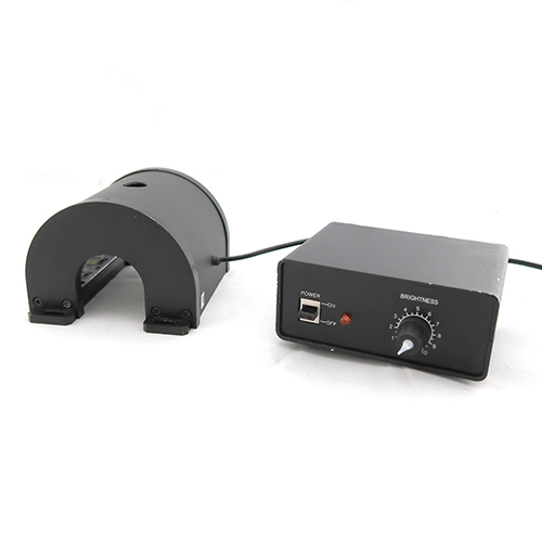
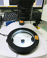
There are several types of transmitted light devices.
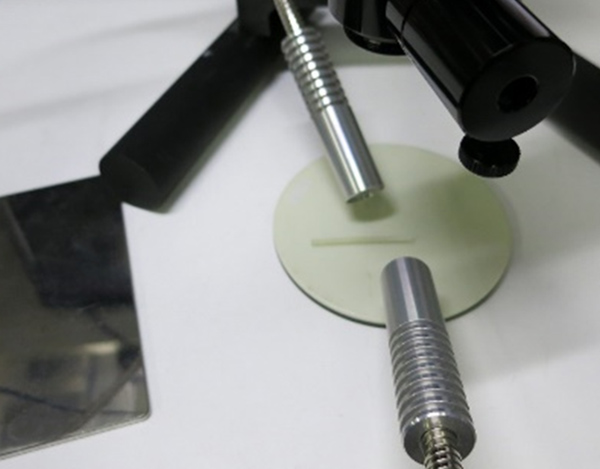
・Diffused transmitted light (general type of transmitted light)
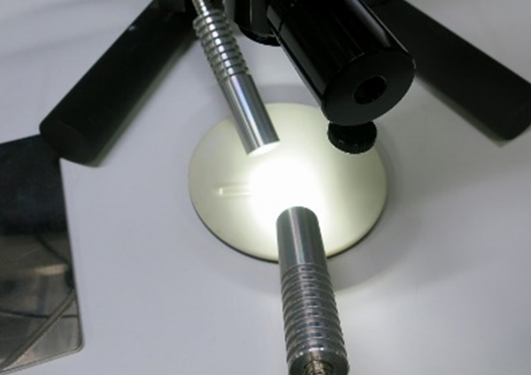
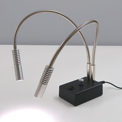
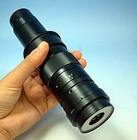
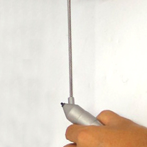
・Parallel transmitted light (compact transmitted light suitable for dimension measurement)
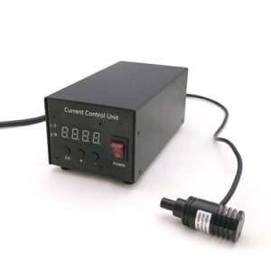
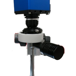
・Telecentric light (high-precision, large-scale light used in projectors and similar devices)
Of course, telecentric light is the most suitable for dimension measurement.
However, it is large in size and comes with a significantly higher cost (it is integrated into high-precision projectors and dimension measuring instruments).
For general use, we recommend parallel transmitted light.
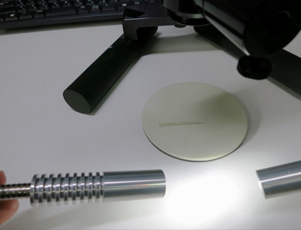
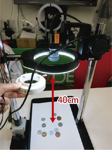
The lighting method becomes particularly important when measuring samples with significant thickness.
(For thin samples, the difference is less noticeable.)
 |
|
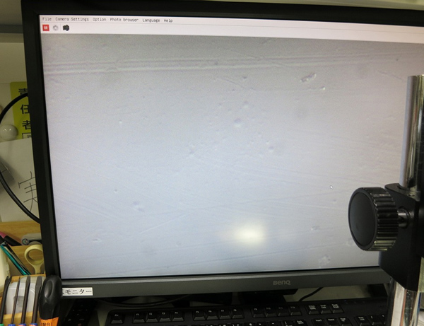
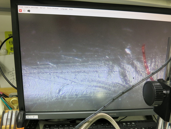
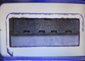
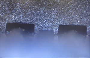
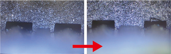
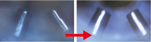
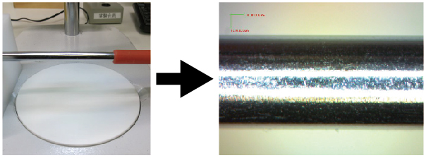
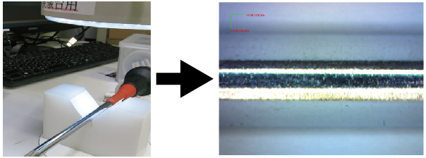
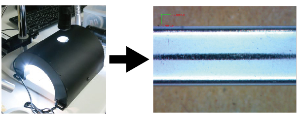
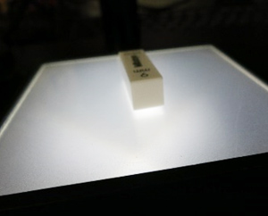
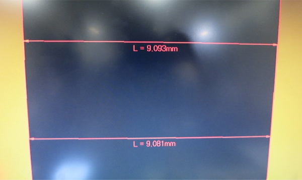
We measured the Mitutoyo block gauge with a width of 9 mm.
|
| <Diffused transmitted light> |
|
<Parallel transmitted light> |
 |
|
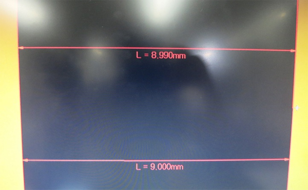 |
* Each was measured twice consecutively.
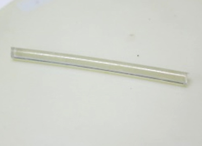
For items such as glass scales, either lighting method is suitable.
However, when the specimen has thickness, we recommend parallel transmitted light.
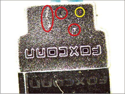
・Adjust the brightness to a “darker” setting
Generally, adjust to a “darker” setting.
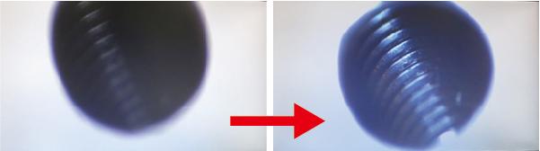
Increasing the illuminance causes the white areas (bright spots) to expand.
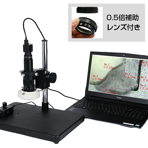
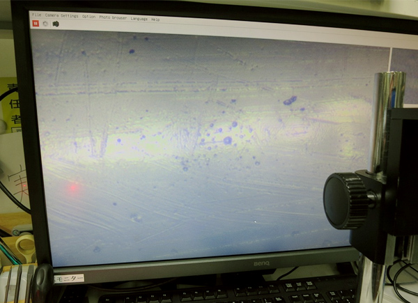
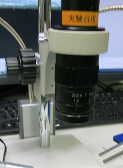
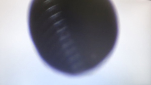
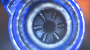
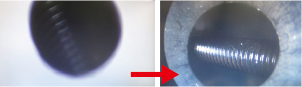
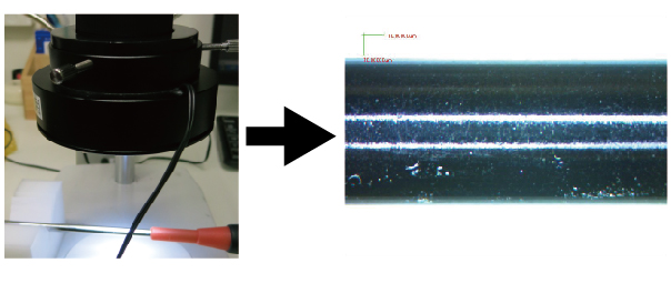
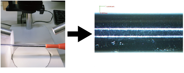
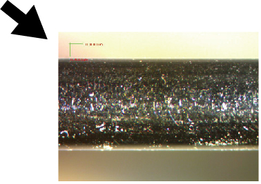
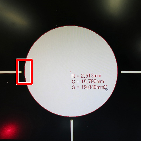
We measured a glass scale with a radius of 2.5 mm using our non-calibrated microscope.
(When the measured area is white, increasing the brightness causes it to appear larger.)
* To eliminate variation due to the operator, the “Edge Automatic Detection Mode (A)” was set.
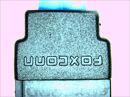
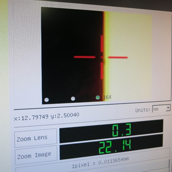
| <When adjusted to a brighter setting> |
|
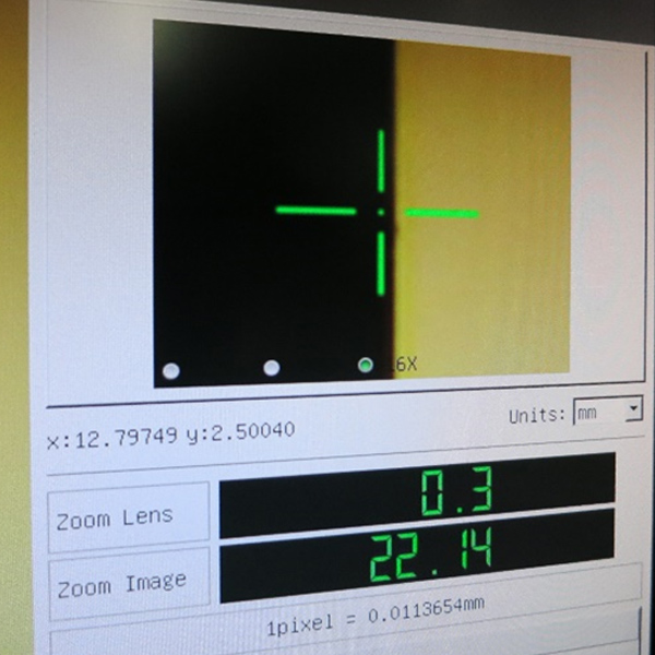
<When adjusted to a darker setting> |
 |
|
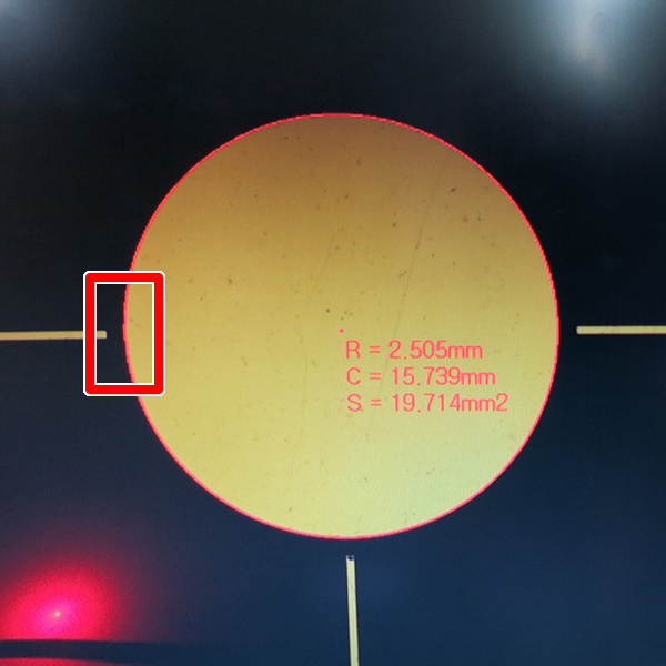 |
| ⇓ Zoom in on the area within the red frame above |
|
⇓ Zoom in on the area within the red frame above |
 |
|
 |
|
With our non-calibrated microscope, it is recommended to adjust to a slightly darker setting, within the range where the automatic edge detection mode (A) functions stably.
 |
|
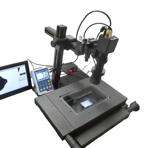
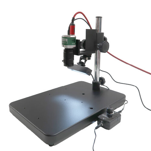
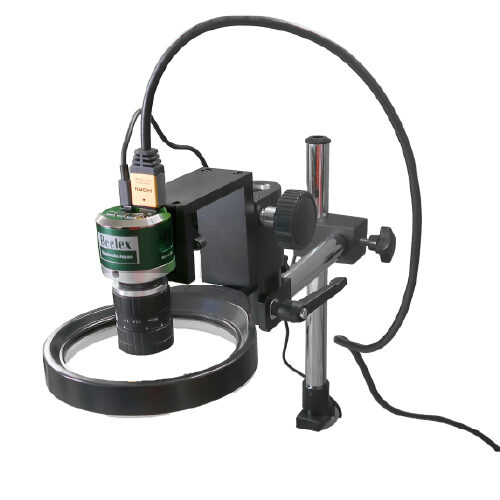
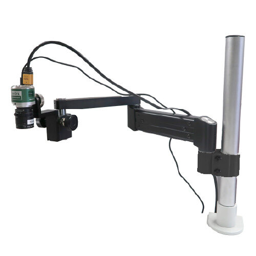
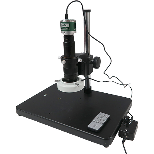
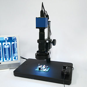
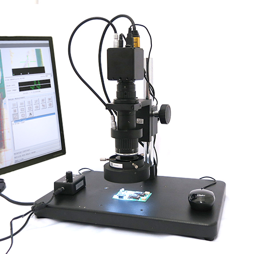
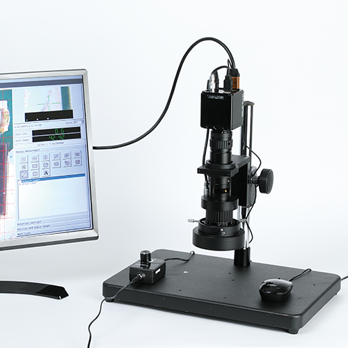
Dimension measurement (auto-calibration) microscope (medium magnification)
CT200HD
|
 |
|
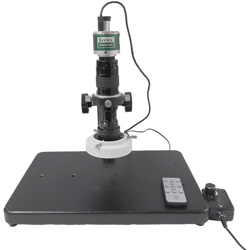
Dimension measurement (auto-calibration) microscope (high magnification)
CT200HD-H
|