1. What is dendrite arm paging?
Dendrite arm spacing is a measurement method used to evaluate the structure of aluminum alloys.
A dendrite is a dendrite formed by solidified metal crystals.
The primary arm of the main axis and the secondary arms that develop on the sides of this arm are observed in a dendritic shape.
Measuring the distance between the centers of the arms provides an indicator of the density and shape of the dendrite.
This is affected by the estimation of the solidification rate and cooling rate of the metal, and the distribution of crystal precipitates.
Measuring the dendrite arm spacing reveals the quality and mechanical properties of the casting.
In recent years, it has become a very important test.
2. How to measure dendrite arm spacing
Pretreatment is performed in the same manner as general metal structure observation, and it can be performed using a microscope image.
The main steps of pretreatment are:
① Cutting
②Resin embedding
③Polishing
④Mirror finish
⑤Etching treatment with chemicals
⑥Washing with water
⑦Remove moisture with a hair dryer
The pretreatment process alone requires considerable effort and time.
After the pretreatment mentioned above, the dendrite arm spacing is measured using a microscope or microscope image.
There are two ways to measure dendrite arm spacing:
・Quadratic branch method
・Intersection method
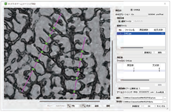
The quadratic branch method is a method of selecting areas where quadratic arms are aligned and finding the average value of the intervals.
The intersection line method is a method used when it is difficult to select aligned secondary arms in a structure consisting of granular crystals with little directionality.It is a method that is used when it is difficult to select aligned secondary arms. This is a method to calculate.
It takes a lot of effort and time for humans to perform these measurement operations in analog form.
Therefore, this time we will introduce an efficient method for measuring dendrite arm spacing using the software below.
3. How to efficiently measure dendrite arm spacing using software
We will introduce how to efficiently measure using “Image analysis software WinROOF Material Option”.
This software allows you to calculate measurement results using the “quadratic branch method” of the methods described above.
Our microscope cameras are compatible with this “image analysis software WinROOF material option” and can perform measurements in live images.
(Of course, it is also possible to load multiple images taken in advance.)
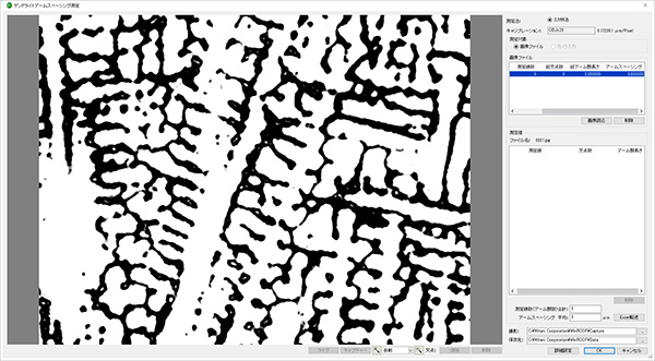
Step 1
Open the dendrite arm spacing measurement screen and load the image.
This measurement is typically performed on multiple fields of view (images).
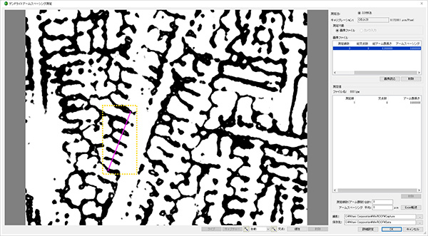
Step 2
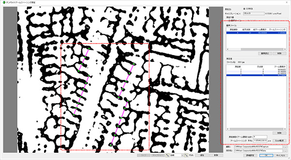
On the loaded image, use the mouse to set the “measurement line” (inside the yellow frame in the figure below) at the location of the arm group where arm paging measurement will be performed.
Specify the boundary of the secondary arm as the intersection on the set measurement line.
Step 3
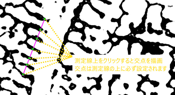
Click on the boundary between the measurement line and the secondary arm to add an intersection point. (With automatic intersection detection function)
Step 4
Once you have specified the intersection point for one arm group, repeat the process of setting the measurement line and specifying the intersection point for other arm groups within the field of view.
Measurement information is updated on the screen in real time, allowing you to check the current arm paging value, etc. Specify a sufficient number of intersection points while switching images (field of view).

supplement
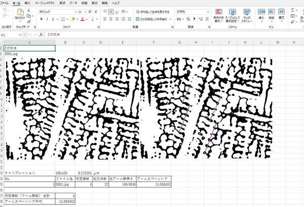
Measurement results can also be transferred to Excel.
4. summary
Inspections that require specialized expertise, such as dendrite arm spacing measurements (DAS measurements), are performed visually by skilled personnel, who spend a lot of time on them.
By installing this software,
・Short testing time by reducing testing burden
・Standardization of inspection
・Improving the vulgarization of testing
This leads to considerable efficiency gains.
It is also possible to output a report showing the evaluation results, making reporting the results smooth.
For the “image analysis software” used this time, please see the product page below.

